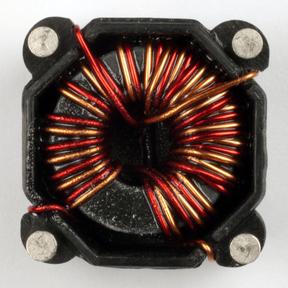
L10/L13 Series Qtr-Pak® & Qtr-Pak II™
High Performance, High Reliability, SMT Dual Inductors/1:1 Flyback Transformers
L10 Series: -40 to 125˚C Operating Range
L13 Series: -40 to 150˚C Operating Range
- High energy storage in high reliability SMT package.
- Low EMI, self-shielding toroid based magnetics.
- Pins: 100% matte Sn over Ni plating over brass.
- Feet available to RoHS reflow temps.
- Dual windings for SEPIC, ZETA and 1:1 transformer circuits.
- Variations quickly available: turns ratios; voltage isolation, etc.
- BUY NOW -- Call 952-894-9590
L10-10xx QTR-Pak®
| Parallel | Series | |||||||
|---|---|---|---|---|---|---|---|---|
| BH Part Number | Loc (uH) @0ADC | Typical Loc (uH) Biased | Max Current (Adc) | Parallel DCR (Ohms) | Loc (uH) @0ADC | Typical Loc (uH) Biased | Max Current (Adc) | Series DCR (Ohms) |
| L10-1004 | 1.36 | 1.1 | 11.87 | 0.004 | 5.4 | 4.3 | 5.94 | 0.015 |
| L10-1005 | 1.85 | 1.5 | 10.17 | 0.004 | 7.4 | 5.9 | 5.09 | 0.018 |
| L10-1006 | 2.41 | 1.9 | 8.90 | 0.005 | 9.7 | 7.7 | 4.45 | 0.020 |
| L10-1007 | 3.05 | 2.4 | 7.91 | 0.007 | 12.2 | 9.8 | 3.96 | 0.029 |
| L10-1008 | 3.77 | 3.0 | 7.12 | 0.010 | 15.1 | 12.1 | 3.56 | 0.040 |
| L10-1009 | 4.56 | 3.6 | 6.47 | 0.011 | 18.2 | 14.6 | 3.24 | 0.045 |
| L10-1010 | 5.43 | 4.3 | 5.94 | 0.012 | 21.7 | 17.4 | 2.97 | 0.049 |
| L10-1011 | 6.37 | 5.1 | 5.48 | 0.013 | 25.5 | 20.4 | 2.74 | 0.053 |
| L10-1012 | 7.39 | 5.9 | 5.09 | 0.018 | 29.6 | 23.6 | 2.54 | 0.072 |
| L01-0726 | 8.48 | 6.8 | 4.75 | 0.019 | 33.9 | 27.1 | 2.37 | 0.077 |
| 501-0726 | non-RoHS version of L01-0726 available by special order | |||||||
| L10-1016 | 12.21 | 9.8 | 3.96 | 0.023 | 48.9 | 39.1 | 1.98 | 0.092 |
| L10-1017 | 13.61 | 10.9 | 3.75 | 0.024 | 54.4 | 43.6 | 1.87 | 0.097 |
| L10-1018 | 15.08 | 12.1 | 3.56 | 0.041 | 60.3 | 48.3 | 1.78 | 0.163 |
| L10-1019 | 18.25 | 14.6 | 3.24 | 0.045 | 73.0 | 58.4 | 1.62 | 0.180 |
| L10-1020 | 21.72 | 17.4 | 2.97 | 0.049 | 86.9 | 69.5 | 1.48 | 0.196 |
| L10-1021 | 25.49 | 20.4 | 2.74 | 0.066 | 101.9 | 81.6 | 1.37 | 0.264 |
| L10-1022 | 29.56 | 23.6 | 2.54 | 0.071 | 118.2 | 94.6 | 1.27 | 0.284 |
| L10-1023 | 33.93 | 27.1 | 2.37 | 0.076 | 135.7 | 108.6 | 1.19 | 0.304 |
| L10-1024 | 38.60 | 30.9 | 2.23 | 0.104 | 154.4 | 123.5 | 1.11 | 0.415 |
| L10-1025 | 43.58 | 34.9 | 2.09 | 0.110 | 174.3 | 139.5 | 1.05 | 0.441 |
| L10-1026 | 48.86 | 39.1 | 1.98 | 0.117 | 195.4 | 156.3 | 0.99 | 0.467 |
| L10-1027 | 54.44 | 43.6 | 1.87 | 0.155 | 217.8 | 174.2 | 0.94 | 0.622 |
| L10-1028 | 60.32 | 48.3 | 1.78 | 0.164 | 241.3 | 193.0 | 0.89 | 0.654 |
| L10-1029 | 66.50 | 53.2 | 1.70 | 0.172 | 266.0 | 212.8 | 0.85 | 0.687 |
| L10-1032 | 86.86 | 69.5 | 1.48 | 0.243 | 347.4 | 278.0 | 0.74 | 0.972 |
| L10-1037 | 126.82 | 101.5 | 1.23 | 0.373 | 507.3 | 405.8 | 0.61 | 1.491 |
| L10-1038 | 135.72 | 108.6 | 1.19 | 0.386 | 542.9 | 434.3 | 0.59 | 1.543 |
| L10-1042 | 174.32 | 139.5 | 1.05 | 0.437 | 697.3 | 557.8 | 0.52 | 1.748 |
| L10-1043 | 184.73 | 147.8 | 1.02 | 0.450 | 738.9 | 591.1 | 0.51 | 1.800 |
| L10-1044 | 200.90 | 160.7 | 0.98 | 0.596 | 803.6 | 642.9 | 0.49 | 2.384 |
| L10-1047 | 247.35 | 197.9 | 0.88 | 0.661 | 989.4 | 791.5 | 0.44 | 2.645 |
| L10-1048 | 272.38 | 217.9 | 0.84 | 0.694 | 1089.5 | 871.6 | 0.42 | 2.776 |
- Parallel DCR = DCR per winding / Series DCR = DCR per winding x 2.
- Inductance measured at 25˚C.
- Max. current measured at 25˚C, 20% inductance roll-off. Above 85˚C operating temp., max. current is reduced.
- Plots of Inductance vs. Current available for all above parts. Contact BH.
- T&R available: 400 per 13" reel, 1,200 minimum release. Smaller quantities shipped in JEDEC trays.
- Highlighted part numbers are standard products. Others are available as non-standard parts with longer lead times.
- RoHS parts designated with “L” (e.g., L10-1007). Are electrically the same as non-RoHS designated with “5” (e.g., 510-1007).
- RoHS “L” and non-RoHS “5” Catalog Parts use pins with matte Sn over Ni barrier over brass. Wire/pin solder is SAC or Sn63/Pb37, respectively.
- Above parts available with Sn90/Pb10 plated pins on a “custom” part basis. Contact us for details.
L13-10xx QTR-Pak II™
High Temperature (150˚C Operating)
| Parallel | Series | |||||||
|---|---|---|---|---|---|---|---|---|
| Part Number | Loc (uH) @0ADC | Typical Loc (uH) Biased | Max Current (Adc) | Parallel DCR (Ohms) | Loc (uH) @0ADC | Typical Loc (uH) Biased | Max Current (Adc) | Series DCR (Ohms) |
| L13-1000 | 1.90 | 1.24 | 11.79 | 0.006 | 7.60 | 4.94 | 5.89 | 0.024 |
| L13-1001 | 2.30 | 1.49 | 10.72 | 0.009 | 9.20 | 5.98 | 5.36 | 0.034 |
| L13-1002 | 2.74 | 1.78 | 9.82 | 0.009 | 10.9 | 7.11 | 4.91 | 0.037 |
| L13-1003 | 3.21 | 2.09 | 9.07 | 0.013 | 12.8 | 8.35 | 4.53 | 0.051 |
| L13-1004 | 3.72 | 2.42 | 8.42 | 0.014 | 14.9 | 9.68 | 4.21 | 0.055 |
| L13-1005 | 4.28 | 2.78 | 7.86 | 0.015 | 17.1 | 11.1 | 3.93 | 0.058 |
| L13-1006 | 4.86 | 3.16 | 7.37 | 0.020 | 19.5 | 12.6 | 3.68 | 0.079 |
| L13-1007 | 5.49 | 3.57 | 6.93 | 0.021 | 22.0 | 14.3 | 3.47 | 0.084 |
| L13-1008 | 6.16 | 4.00 | 6.55 | 0.022 | 24.6 | 16.0 | 3.27 | 0.089 |
| L13-1009 | 6.86 | 4.46 | 6.20 | 0.023 | 27.4 | 17.8 | 3.10 | 0.094 |
| L13-1010 | 7.60 | 4.94 | 5.89 | 0.031 | 30.4 | 19.8 | 2.95 | 0.124 |
| L13-1011 | 9.20 | 5.98 | 5.36 | 0.034 | 36.8 | 23.9 | 2.68 | 0.136 |
| L13-1012 | 10.9 | 7.11 | 4.91 | 0.037 | 43.8 | 28.5 | 2.46 | 0.149 |
| L13-1014 | 14.9 | 9.68 | 4.21 | 0.055 | 59.6 | 38.7 | 2.11 | 0.220 |
| L13-1015 | 17.1 | 11.1 | 3.93 | 0.073 | 68.4 | 44.5 | 1.96 | 0.293 |
| L13-1017 | 22.0 | 14.3 | 3.47 | 0.083 | 87.9 | 57.1 | 1.73 | 0.333 |
| L13-1018 | 24.6 | 16.0 | 3.27 | 0.088 | 98.5 | 64.0 | 1.64 | 0.352 |
| L13-1020 | 30.4 | 19.8 | 2.95 | 0.125 | 122 | 79.0 | 1.47 | 0.500 |
| L13-1021 | 33.5 | 21.8 | 2.81 | 0.131 | 134 | 87.1 | 1.40 | 0.525 |
| L13-1022 | 36.8 | 23.9 | 2.68 | 0.137 | 147 | 95.6 | 1.34 | 0.550 |
| L13-1024 | 43.8 | 28.5 | 2.46 | 0.189 | 175 | 114 | 1.23 | 0.757 |
| L13-1025 | 47.5 | 30.9 | 2.36 | 0.197 | 190 | 124 | 1.18 | 0.788 |
| L13-1027 | 63.9 | 41.5 | 2.03 | 0.283 | 256 | 166 | 1.02 | 1.132 |
| L13-1029 | 82.8 | 53.8 | 1.79 | 0.322 | 331 | 215 | 0.89 | 1.288 |
| L13-1031 | 104 | 67.6 | 1.59 | 0.458 | 416 | 271 | 0.80 | 1.834 |
| L13-1034 | 141 | 91.3 | 1.37 | 0.533 | 562 | 365 | 0.69 | 2.131 |
| L13-1035 | 154 | 100 | 1.31 | 0.708 | 616 | 400 | 0.65 | 2.833 |
| L13-1037 | 182 | 119 | 1.20 | 0.771 | 730 | 474 | 0.60 | 3.085 |
| L13-1038 | 198 | 128 | 1.16 | 0.803 | 791 | 514 | 0.58 | 3.211 |
| L13-1040 | 230 | 149 | 1.07 | 0.866 | 920 | 598 | 0.54 | 3.462 |
| L13-1042 | 265 | 172 | 1.00 | 1.175 | 1,058 | 688 | 0.50 | 4.701 |
- Parallel DCR = DCR per winding / Series DCR = DCR per winding x 2.
- Inductance measured at 25˚C.
- Max. current measured at 25˚C. Max. temp and inductance values stable at high temps. Contact us for details.
- Plots of Inductance vs. Current available for all above parts. Contact BH.
- T&R available: 400 per 13" reel, 1,200 minimum release. Smaller quantities shipped in JEDEC trays.
- Cores have been tested at 200˚C for 10,000 hours with no harmful effects.
- For above inductor/transformer values that can operate to 200˚C, see Page 23.
© 2026 BH Electronics
12219 Wood Lake Drive
Burnsville,
MN
55337
Phone: 952-894-9590
Fax: 952-894-9380